This is the tutorial dedicated to THT, the through-hole KIT KeyChainino’s version.
In this page you learn, step-by-step, how to mount and solder all the components on the PCB to make your THT.
Download the schematics and the eagle file here:
https://github.com/alessandromatera/KeyChainino/tree/master/THT
Step 1: Mount the ATTiny84 microcontroller
After pulling out the micro from its case, you need to slightly bend its pins in order to fit it in the PCB.
To bend the pins grab both ends and rock the pins against the table. Once all the pins are parallel, locate the U-shaped notch in one end. Make sure that this end goes into the notched-end indicated on the silkscreen and then insert the microcontroller.
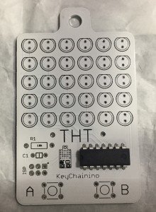
After that, flip the board and solder all the microcontroller pins.
Step 2: Mount the resistor and the capacitor
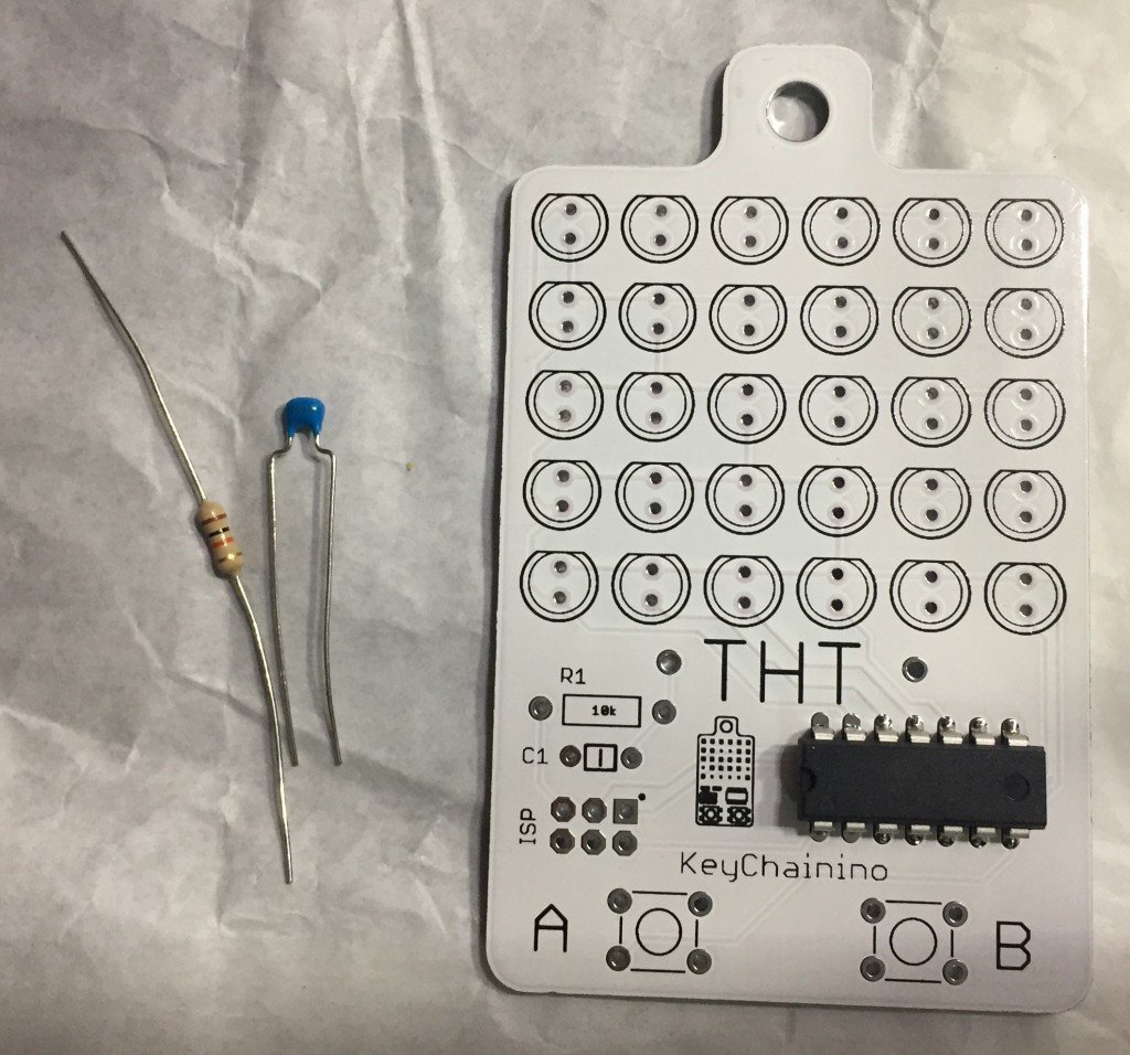
First you need to bend the 10k resistor’s and put the resistor in the R1‘s holes then bend the resistor’s pins.
Next insert the 100nF Capacitor in the C1 holes. This type of capacitor is NOT polarized, so you can put in the way you want. Then bend the Capacitor’s pins.
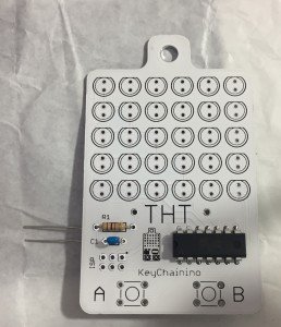
Flip the board and solder the resistor’s and capacitor’s pins and finally cut them.
Step 3: Mount the two push buttons
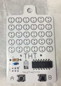
Put the two push buttons in order to have the button’s pins in the left and right side.
After, flip the board, solder the 8 pins and next cut the remaining pins.
Step 4: Solder the LEDs on the PCB
In this step you’ll put all the LEDs in the THT’s PCB.
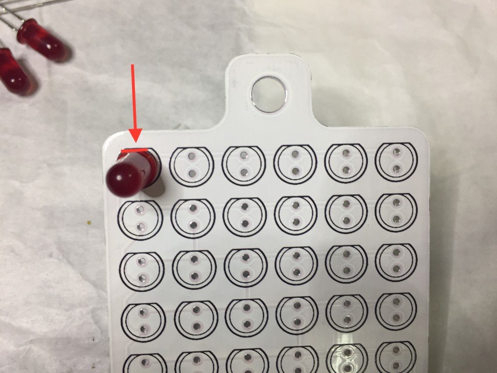
First you must know that the LED is a polarized components. This means that it must be put in one specific way.
The LED has two pins: Anode and Cathode.
As shown in the first picture, the CATHODE (the short pin) MUST be placed in the upper hole, while the ANODE must be placed in the bottom hole.
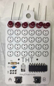
Now you can insert every LEDs in the first top line in the TOP PCB side, which is the side where is located the label THT.
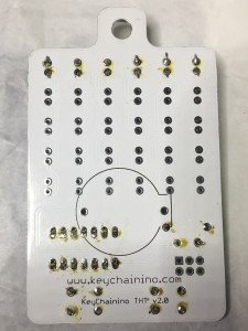
After positioning the LEDs, flip the board and bend the LEDs’ pins as shown in the following picture.
Next solder the LEDs’ pins.
After that, cut the LEDs’ pins.
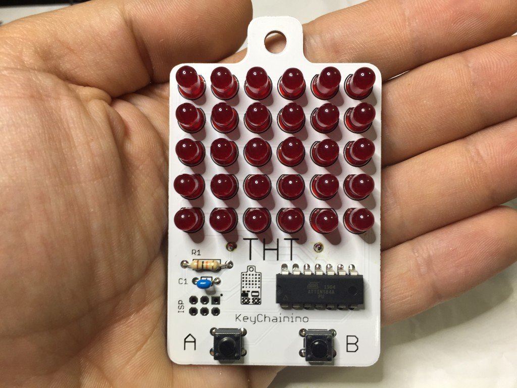
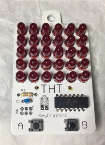
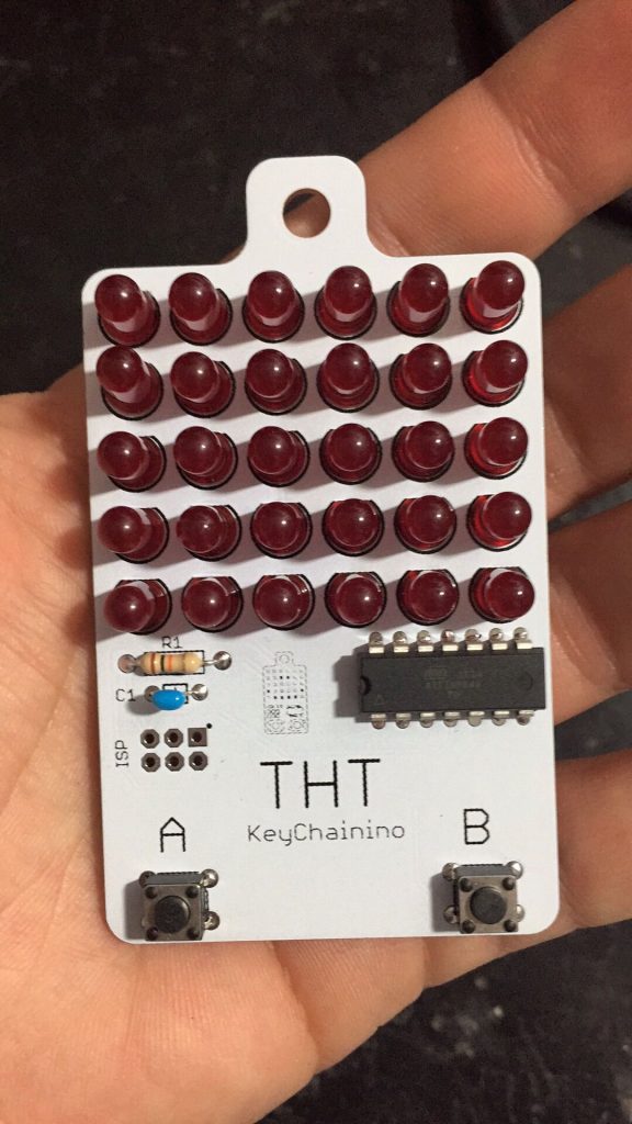
Now you can do the same thing to the other LEDs. Here’s the final result
Step 5A: Mount the CR2032 battery holder THT (Old Version)
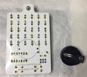
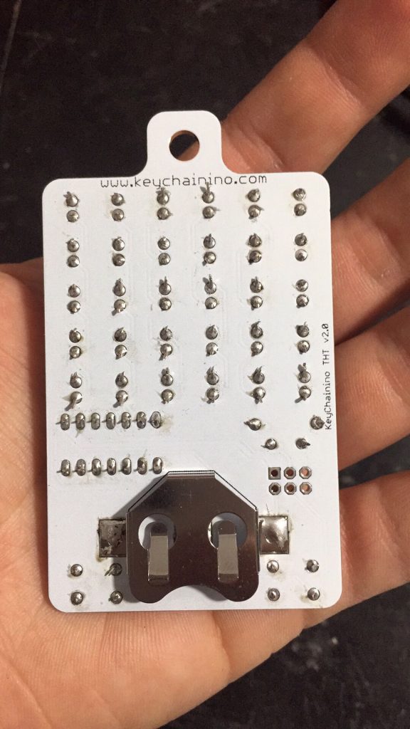
The battery holder is mounted top-down. This means that you have to put the battery holder in the bottom side of the PCB.
Put the battery holder in the right way following the silkscreen on PCB’s bottom.
After putting the battery holder in the bottom side, flip the board and next you need to solder the two pins near the resistor and the microcontroller, after the last LEDs line.
Be careful on soldering this last two pins because you have to pay attention to not touch, with the soldering iron, the other components.
Step 5B: Mount the CR2032 battery holder SMD (New Version)
I have updated the board in order to make you easily solder the battery older.
In this new version you have to:
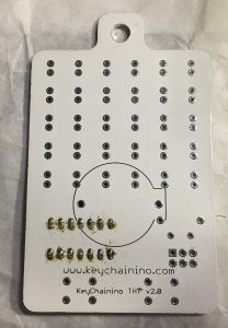
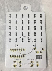
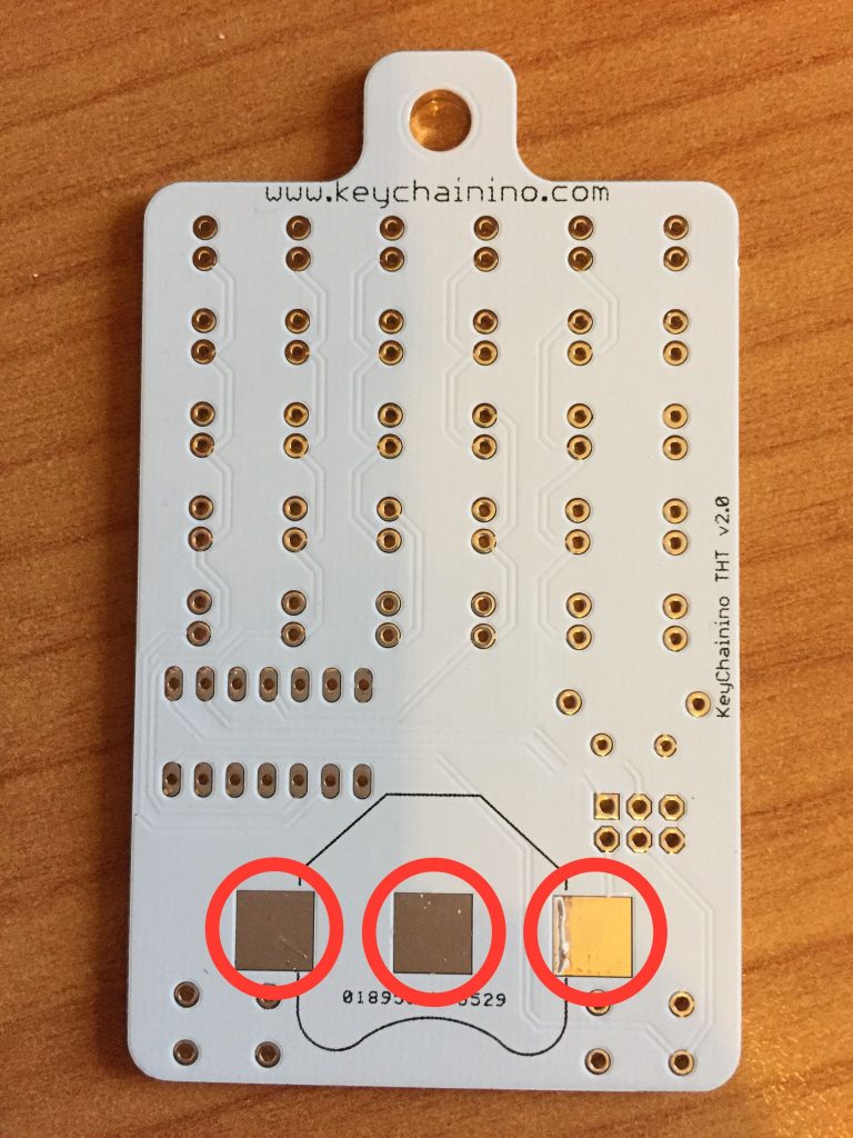
- Tin all the 3 pads on the back of the board (circled in red in the bottom image)

- Put the battery holder on the pads and attach it with some tape (or hold it with a screwdriver).
⚠️ WARNING: Don’t hold it with your hands because the battery holder could get very HOT! ⚠️ - Solder the battery holder by put the iron tip on the two external pads.


Here we are!
You have completed the THT assembly operation 🙂
You can also follow the video below made by Antonio Mancuso. Take a look at his blog!
Now its time to burn the bootloader on the chip using the ISP header (that you can solder if you want), and then upload your awesome sketch!
To do that, follow this guide here:
If you have any questions, write a comment below!
THT in Action!
- Tin all the 3 pads on the back of the board (circled in red in the bottom image)













Appreciate the tutorial. May get one of these key chains. This is quite interesting.
Ive made my own smd version,needs a little change but it nearly done
When it’s done, can you send me a photo so I can put in the blog?
Thanks
Hi what size smd led do you use,I’ve opted for 1206 I think they be OK and ime choosing violate color!just waiting for my boards from osh park can’t wait to build!
Hi Dunk,
Thanks for your appreciation 🙂
I used 0805 LEDs package!
Best
Great work by the way and so well set out,love your tutorials too,I’ve learned a lot from this project,well done!